A Simple Electrical Circuit Breakdown
Table of Contents
Introduction
I recently joined a two-year program to become an electronics technician, and things are getting hands-on from the start (ó﹏ò。). In one of my very first classes, our electrical teacher handed us a practical assignment: break down and describe a simple switchboard from scratch. Since I’m documenting my journey into the world of electronics, I figured—why not turn my homework into a quick guide? So here is my breakdown of the task, starting with a look at each component in the exact order that power flows through the system.
The Circuit
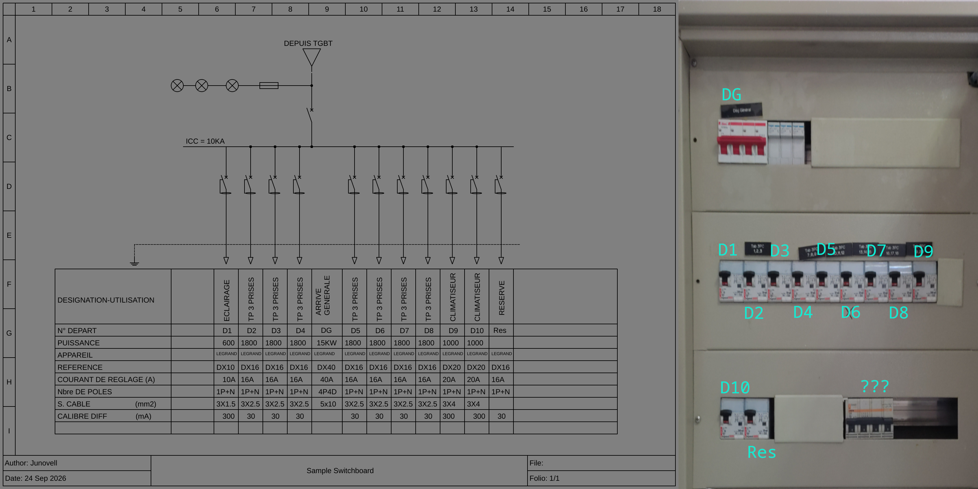
To get a clearer picture of what we are dealing with, I recreated my teacher’s paper using QElectroTech so it’s readable and next to it is the image of the switchboard it’s representing. I also put the ID of each breaker as it was defined in the diagram’s table.
This specific circuit represents a simple classroom switchboard layout. Here is the general layout of what it has:
Incoming Power Supply: A main 3-phase circuit breaker (the big red breaker at the top) that acts as the primary switch and protection for the whole board.
Distribution: Power flows down from the main breaker to 11 single-phase breakers, which split the load into smaller individual circuits.
Standardization: All of this is drawn using standard IEC symbols, which are the global standard for electrical, electronic, and architectural schematics.
Components
To break this down for my own notes, I’m going to follow the exact path of the electricity starting from the main incoming supply at the top and working my way down to the individual components.
0. The Power Source
Before electricity can do anything in the switchboard, it has to enter the system from the main grid, but since this is a classroom’s dashboard, then then electricity is coming from the building’s main electrical room.
Which is what this triangle down here represents:
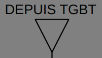
“DEPUIS TGBT” is french for “From the Main Low Voltage Switchboard”, it means that our switchboard isn’t an independent power source; rather it’s being fed upstream from the building’s main electrical distribution panel.
1. The Diagnostic Circuit
Right below the main supply line and on it’s left, you’ll notice a branch coming off to the side like a little electrical appendix:
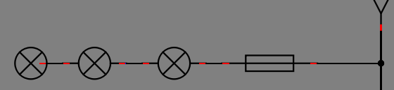
On the diagram, this is symbolized by a single fuse (a rectangle with a line through it) attached in series with three lamps (circles with an X inside).
Honestly tho? From my beginner’s perspective, this part of the diagram is pretty misleading.
Why? Because when you look at the actual physical switchboard, the reality looks a bit different (excuse the poor camera quality):
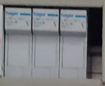
Instead of just one fuse and a shared string, the real board actually has three separate fuses, one for each of the three incoming phases. Each phase feeds into its own fuse and then outputs to its own individual indicator lamp.
This creates a practical diagnostic tool: if one phase drops out or experiences a fault, only the corresponding lamp for that specific phase turns off. It gives us an instant visual warning of which line is having issues without needing to test each phase manually.
3. The Main 3-Phase Circuit Breaker
Now we can finally talk about the big RED elephant in the closet: the main 3-phase circuit breaker.
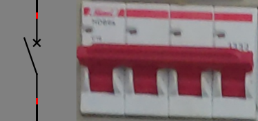
On the diagram, it’s drawn using a standard circuit breaker symbol, but seeing it on paper doesn’t quite do justice to what it actually handles.
first what does a 3-phase circuit breaker even mean? well it’s actually very simple, it’s just 3 live wires (each carrying power from the grid) tied together into a single breaker, which is the red one we see in the image above.
But how much power can it deliver tho? is a question i had too, at first i had the naive idea of just summing them up together and calling it a day so 230V x 3 = 690V and voila ◝(ᵔᗜᵔ)◜…
Yeah, well, that’s not quite how it works (ᵕ—ᴗ—).
while my naive idea might seem intuitive at first, we need to understand how 3 phases actually work. Instead of stacking up, they deliver power all at the same time but with their phase shifted by 120°, something like this:
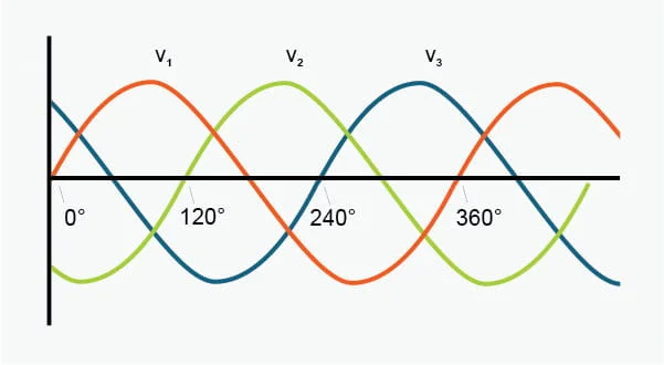
Each wave represents a different live wire. Because they peak at different times, the maximum voltage difference between any two of them is calculated as: 230V x √3 = ~398V or 400V (we’ll discuss how that rounding up happens in the future).
Looking at the table at the bottom of the diagram, in the “ARRIVE GENERALE” column, we can read these specs for the breaker:
- Brand & Model: Legrand (which is a French industrial group specializing in electrical parts)
- Reference: DX series / dx40
- Rating: 40A (this is the maximum current intensity the breaker can allow before it shuts down to protect the circuit)
- Power Rating: 15 kW (the maximum power limit it can handle)
- Number of Poles: 4P4D (4 poles, meaning it switches and protects all three live phases plus the neutral.)
- Cable Section: 5x10 mm² (meaning a 5-conductor cable with three phases, neutral, and earth with a 10mm² cross-section to handle that 15 kW load safely)
4. The Council of the 11 Single-Phase Breakers
Right after our main 3-phase switch, the power doesn’t just go straight to a single output. Instead, it gets chopped up and distributed. On the schematic, right next to each other from left to right, sit 11 single-phase breakers.
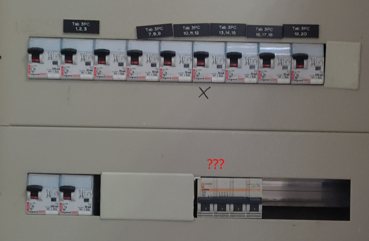
what are they for you ask? simple, it’s the same concept in programming as “separation of concerns”. While the main breaker controls the whole board, these 11 individual breakers step down the power to feed specific zones—like different rows of classroom benches, lighting circuits, or individual outlet groups. for example we can already see in the description table 2 of them are going for air conditioning. So if a student creates a short circuit on bench number 4, only that specific breaker trips, leaving the rest of the classroom with power (and saving us from the awful heatwave this summer).
The Big Security Upgrade: RCBOs (Disjoncteurs Différentiels)
you should have also noticed that these breakers don’t use the same symbol as the main one, that’s the symbol of an RCBO (Residual Current Circuit Breaker with Overcurrent protection) or disjoncteur différentiel in french.
but what does that mean? Essentially it’s a two-in-one device. It does standard overcurrent/short-circuit protection (like a normal breaker), plus it monitors the balance between the phase and neutral current to protect humans from electrocution (acting like a residual current device/RCD). If even a tiny bit of current (like 30mA) leaks out—say, someone touches a live wire it trips instantly to save a life.
5. The Line
But let’s not get ahead of ourselves, you may have missed it, or even ignored it, but right above the breakers there’s a horizontal line with the label “ICC = 10KA” on top of it

Let’s start with the line first, there are 2 possible explanations of it that i got from 2 different sources
- My electrical engineer friend said that the breakers are connected in parallel one by one from the main breaker, so each small breaker takes 2 wires from the main one (any live wire and one neutral) then a branch is created to the next breaker, thus connecting them manually one by one in parallel.
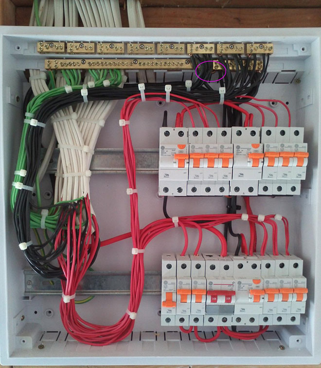
- GEMINI said that it could be a Busbar (or Peigne d’alimentation in french) which is a large piece of copper connected that takes power from the main breaker and has the small breakers attached to it.
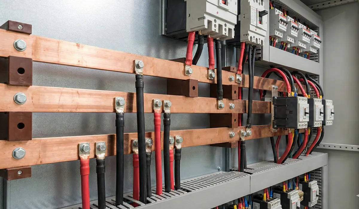
Personally i don’t quite understand how the Busbar works exactly, but simply looking up images for it on DuckDuckGo shows images of industrial switchboards, so i’m leaning into my friend’s explanation for a classroom’s switchboard.
Finally What does ICC = 10KA mean? ICC stands for Short-Circuit Current (Courant de Court-circuit). The “10kA” (10,000 Amps) is a massive safety rating telling us the maximum amount of fault current these breakers can safely interrupt without exploding or catching fire if a catastrophic dead short happens right at the source.
6. Ground 0

Finally all circuit breakers are connect to a dotted line that ends with the symbol for ground meaning that this circuit is secured with a ground connection to absorb all the extra power in the case of a power surge.
7. The Mysterious Breaker
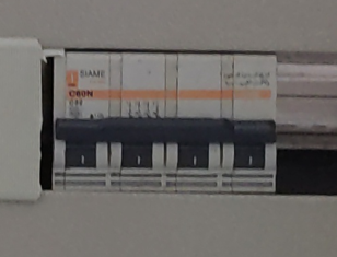
At the bottom of the actual switchboard there’s another 3-phase breaker that doesn’t appear on the diagram, this has to be an extension that was made later on after the switchboard was installed.